

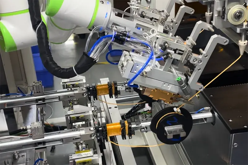
In the on-board chargers of new energy vehicles, coils (typically including high-frequency transformer coils, PFC boost inductors, and LLC resonant inductors) serve as the core components of power conversion. Their winding process directly determines the overall efficiency, power density, thermal performance, and safety of the vehicle under extreme operating conditions. Given that OBCs operate in a unique environment characterized by high voltage (400V/800V platforms), high current, high frequencies (100kHz–300kHz+), and intense vibration, the winding of their coils presents extremely high technical barriers. The following outlines the key considerations in the OBC coil winding process, categorized into four dimensions: material protection, process control, electrical safety, and structural consistency:
I. Wire Protection and Damage Control
OBC coils extensively utilize multi-strand Litz wire or flat copper wire, both of which are highly sensitive to physical friction during the winding process.
• Ultra-mirror finish for wire-guiding systems:
• All wire-guiding pulleys, wire guides, and ceramic tensioner plates on the winding equipment must undergo ultra-mirror polishing (surface roughness ≤ 0.2 μm) or be coated with Teflon.
• Avoid Excessively Small Bending Radii
• The bending radius at coil corners must be strictly limited in accordance with the nominal wire diameter.
II. Precision Tension and Wire Laying Control
Tension and wire laying are critical factors in determining the consistency of coil inductance and spatial efficiency.
• Dynamic Closed-Loop Tension Control:
• The use of a fully automatic servo tensioner is recommended, with a tension decay curve configured (to appropriately reduce tension as the number of turns increases or at turns).
• Zero-Error Wire Arrangement and Aligned Winding:
• The movement step of the wire arrangement servo axis must precisely match the actual outer diameter of the wire (including tolerances) to ensure tight, aligned wire arrangement.
III. Electrical Safety and Insulation Clearances
As a high-voltage component, OBCs are subject to strict automotive-grade standards regarding creepage distance and electrical clearance.
• Physical Isolation at Layer Transition Points:
• When the coil transitions from the first layer to the second, the conductors at the layer boundary are subjected to double the interlayer voltage difference.
• Precautions: During fully automated winding, the layer-change position must be fixed. Typically, high-temperature insulating tape (such as KAPTON polyimide tape) or a barrier must be manually or automatically applied between layers to prevent high-voltage breakdown.
• Protection of Lead-Out Wire Roots:
• After coil winding is complete, the root (i.e., the junction between the coil body and the lead wire) is most susceptible to stress damage during lead bending and extraction.
• Precautions: When bending lead wires, fixtures must be used to secure the root to prevent stress transfer into the coil interior. Lead wires typically require high-voltage heat-shrink tubing or fluoroplastic sleeves to ensure absolute insulation along the path from the coil to the PCB.
IV. Structural Consistency and Compatibility with Subsequent Processes
Coils do not exist in isolation; they are ultimately combined with a magnetic core and assembled into a metal housing.
• Frame Deformation and Tolerance Compensation:
• Tight multi-layer winding generates significant inward compressive stress, which may cause plastic frames (such as LCP or PBT materials) to collapse inward or deform, preventing the subsequent insertion of the magnetic core.
• Precautions: A rigid anti-deformation core (winding mandrel) must be inserted into the bobbin during winding. Additionally, the winding equipment should be equipped with visual or probe inspection to dynamically adjust the winding starting point based on the bobbin’s actual manufacturing tolerances.
• Providing Flow Channels for Encapsulation:
• After the OBC coil is wound, it typically requires overall encapsulation with thermally conductive silicone or epoxy resin.
• Precautions: During winding design, do not solely pursue absolute tight packing. A small process gap (e.g., a 0.5–1.0 mm flow channel) must be left between the coil and the form or between multi-turn coils to ensure the potting compound can fully penetrate and prevent the formation of internal bubbles (bubbles can cause partial discharge under high voltage, accelerating insulation aging).
In OBC coil mass production lines, it is recommended to implement an “in-line 100% inspection” mechanism: directly integrate withstand voltage testing and interlayer impulse testing into the process immediately following the automatic winding machine. This allows for the precise detection and rejection of any latent defects caused by winding abrasions before the coils undergo costly core assembly and potting.